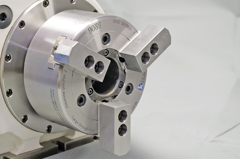
After purchasing our standard chucks, we think there are many cases where customers design their own jaws. In that case, chuck specification calculation is necessary in order to use the chuck safely.
In this article, we will introduce how to check the following items as an approximate estimate.
1. Maximum allowable grip strength
2. Maximum rotation number
3. Grip strength loss due to centrifugal force
For approximate calculations, use the instruction manual that can be downloaded from each chuck product page on our website. Please refer to the graph on the page related to the center height of the gripping part, static grip strength, and input in the instruction manual.

▲From Kitagawa website
▲Graphs in the instruction manual
Before using the graphs, please check the following 4 points in advance.
1. Chuck model
2. Mass moment of the special jaws
3. Distance from the center of rotation of the chuck to the center of gravity of the special jaws
4. Height of gripping part
Specification calculation method using Kitagawa special jaws (for BB208)
This time, as an example, we will use the conditions described in the following figure to calculate the specifications.
▲Outline of the special jaws (for chuck model BB208)
Chuck model : BB208
Mass moment of the special jaw : 192kg・mm (according to the following formula)
istance from the center of rotation of the chuck to the center of gravity of the special jaw : 80 mm
Height of gripping part : 60 mm
The mass moment of the special jaw (kg・mm)
= The jaw mass (kg) x the distance from the chuck center to the special jaw center of gravity (mm) × number of jaws
Calculating the maximum allowable grip strength and input
The value on the vertical axis indicated by the intersection of the gripping center height of 60mm and the grip strength limit line is the maximum allowable grip strength (60kN). The juncture of the intersection and the input-value curve is the input value (cylinder thrust) required to output a static grip strength of 60kN.
Calculating the maximum rotation speed
Extend the line of static grip strength shown in the graph on the right above to the graph on the left, and draw a line at the position of the mass moment of the special jaw calculated on the horizontal axis. The straight line of the rotation speed that passes through the intersection of these two lines is the maximum rotation speed (3700 min-1). The first line extended from the right graph represents the grip strength loss on the vertical axis. When the static grasp strength is 60kN and the rotation number is 3700min-1, the grip strength loss is 40kN.
Note: The maximum rotation number is the rotation number at which the grip strength loss becomes 2/3 of the static grip strength. Cutting resistance and other machining conditions are not taken into consideration.
The results obtained from the above graph are as follows.
1. Maximum static grip strength: 60kN (input: 23.5kN)
2. Maximum rotation speed: 3700min-1
3. Grip strength loss due to centrifugal force: 40kN
⇒ Dynamic grip strength: 60kN - 40kN = 20kN
The explanations given here are just the allowable specifications of the chuck itself. Please note that in actuality, design considerations must take into account the strength of the jaws and the machining load. Please feel free to contact us if you have any questions regarding the design of special jaws.
Last but not least, there is an indispensable lubricant called "CHUCK GREASE" for using chucks. The grip strength as calculated here can be maintained with daily maintenance.
We also recommend the use of CHUCK GREASE to ensure long and safe use.

